How to Select the Right Voltage Level for Oil-Immersed Transformers: Maximize Efficiency and Minimize Losses
Time:2025-07-14 Auther:ZTelec-www.ztelectransformer.com
The voltage level of an oil-immersed transformer is a fundamental design factor that affects its electromagnetic performance, material configuration, insulation system, and energy efficiency. It not only influences the winding and core structure but also plays a crucial role in balancing energy-saving goals with practical operational efficiency. High-voltage transformers often require enhanced insulation and complex winding layouts, which can increase internal leakage flux. In contrast, low-voltage units tend to have simpler structures but may suffer from higher copper losses due to greater current density. This article explores how to scientifically select the voltage level to optimize performance, cost, and energy savings.
![]()
Voltage Level Selection Principles
1. Grid Compatibility
The input and output voltage levels must strictly match the rated voltage of the power grid or the load equipment. Typical configurations include:
10kV/0.4kV: Widely used in commercial and residential distribution systems.
35kV/10kV: Common in regional substations, stepping down transmission voltage for local distribution.
Failure to match voltage levels can result in overloads, reduced efficiency, or even operational hazards.
2. Load Characteristics Adaptation
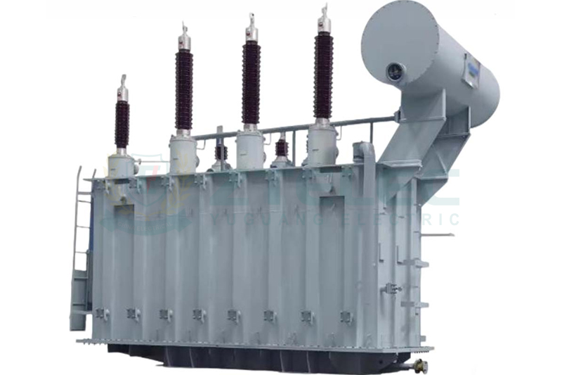
High-voltage transformers (35kV and above): Suitable for long-distance, large-capacity transmission. They operate at lower currents, reducing line losses and copper loss.
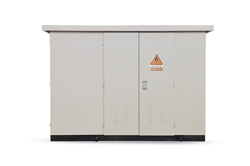
Low-voltage transformers (10kV and below): Ideal for localized, short-distance distribution with lower equipment and installation costs.
3. Short-Circuit Withstand Capability
High-voltage windings must withstand larger fault currents. During design, mechanical strength and dielectric insulation must be carefully verified to prevent failure under fault conditions.
Energy Saving vs. Operational Efficiency
1. Voltage-Dependent No-Load Losses (Iron Loss)
No-load losses originate from core hysteresis and eddy currents and increase with the square of the operating voltage. If the operating voltage exceeds the rated value, iron loss rises significantly.
Optimization Strategy:
– Ensure rated voltage is within ±5% of actual voltage.
– Use tap changers to regulate voltage and avoid prolonged overvoltage operation.
2. Current-Dependent Load Losses (Copper Loss)
Load loss is proportional to the square of the current. Since P = UI, higher voltage results in lower current. For example, when transmitting the same power:
– A 35kV system’s current is only 28.6% of a 10kV system’s.
– Corresponding copper loss is just 8.2% compared to 10kV.
Application Tip: High-voltage transformers are more energy-efficient for high-capacity, long-distance transmission due to significantly reduced current and copper loss.
3. System-Wide Energy Efficiency Evaluation
Optimal Load Rate: Transformers operate most efficiently at 60%–80% of their rated load. Oversizing leads to underloaded, inefficient operation.
Energy-Efficient Standards: Prioritize transformers meeting GB 20052 (China) or IEC 60076 standards. For instance:
– S13 series: >30% reduction in no-load loss vs. S9 series.
– SH15 amorphous alloy transformers: >50% reduction in no-load loss, ideal for long-term savings despite higher upfront cost.
![]()
Other Technical Considerations
1. Temperature Rise and Insulation
Higher voltage requires more robust insulation systems—thicker paper, optimized oil ducts, and better heat dissipation.
Operating limits should be enforced:
– Maximum top oil temperature: ≤85°C
– Exceeding this threshold accelerates insulation aging and reduces lifespan.
2. Voltage Regulation Methods
On-Load Tap Changer (OLTC): Allows ±3×2.5% adjustment under load. Suitable for variable voltage environments like renewables and industrial facilities.
No-Load Tap Changer: More cost-effective. Suitable for stable grid environments, but requires shutdown for adjustment (±5% or ±2×2.5%).
3. Life-Cycle Cost Analysis
High-efficiency transformers have higher upfront costs but much lower operating expenses. Example:
– SH15 vs. S11 (1000kVA): ~30% higher purchase cost, but >12,000 kWh/year savings.
– Payback period: 5–8 years, while service life exceeds 20 years—making it a more economical long-term investment.
Practical Application Recommendations
Industrial Facilities: Where a high proportion of equipment runs at high voltage, 10kV/6kV transformers are ideal. For large-capacity factories, consider 35kV primary incoming transformers.
Renewable Energy Plants: In wind or solar farms, collector lines commonly use 35kV transformers. For step-up grid connections, 110kV transformers minimize transmission loss.
Urban Distribution Systems: 10kV/0.4kV transformers are the standard. Use S13 or higher models with automatic load adjustment to handle residential load fluctuations efficiently.
To achieve the best performance from oil-immersed transformers, voltage levels must be selected scientifically—balancing grid compatibility, load type, and energy efficiency. By combining smart regulation, energy-efficient design, and life-cycle cost control, power system operators can ensure long-term savings and optimal operational safety.