Transformer Capacity Calculation for 2025—A Complete Engineer’s Guide
Time:2025-08-27 Auther:ZTelec-www.ztelectransformer.com
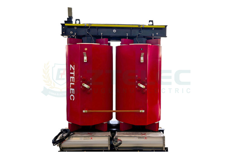
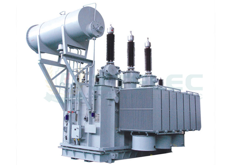
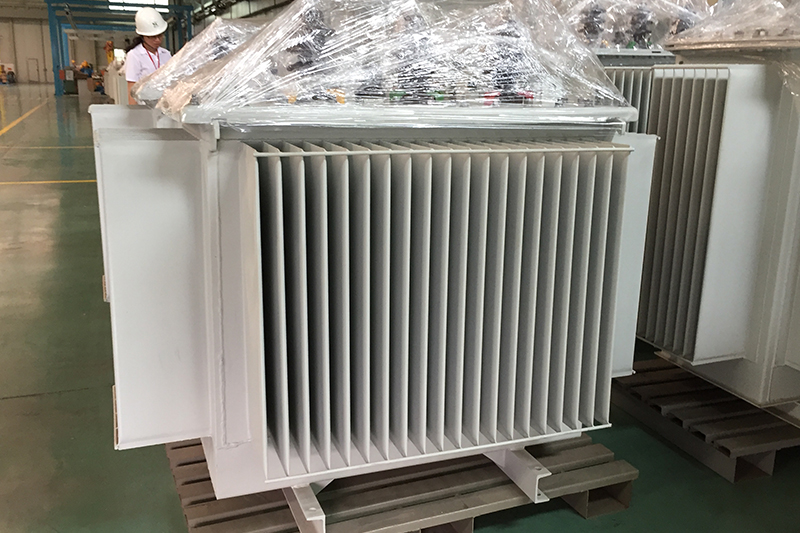
Transformers are essential core equipment in power systems, and selecting the correct capacity is critical for grid stability, efficiency, and economic performance. As energy transformation, digitalization, and new productivity trends accelerate in 2025, transformer sizing requires careful planning and adherence to modern standards. Professional transformer manufacturers now provide advanced guidance and calculation methods to ensure optimal capacity selection for both oil-immersed transformers and dry-type transformers.
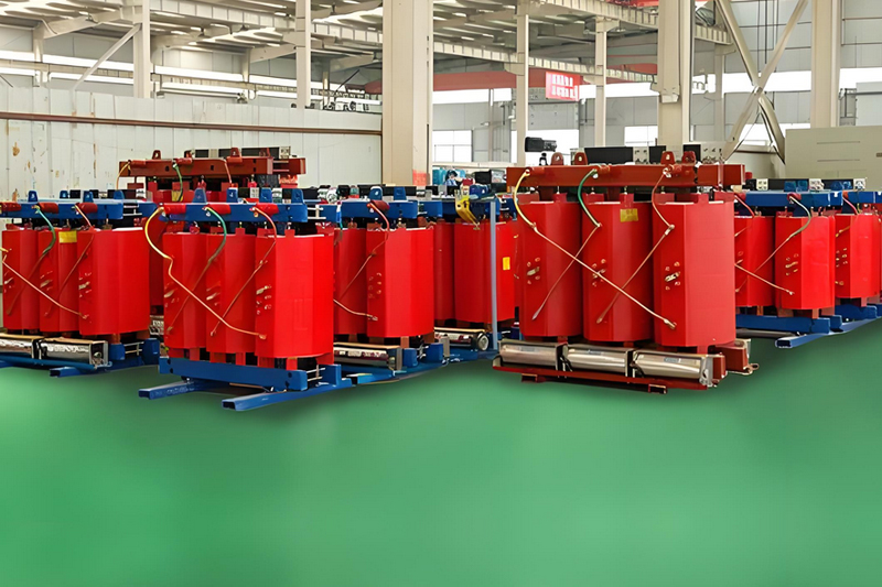
Core Basis and Methods for Transformer Capacity Calculation
The primary goal of transformer sizing is to safely and economically handle the maximum load, including future growth, with an appropriate margin. The standard formula is:
S = ∑Pn × Kt / (cosφ × η)
Where:
S: Required transformer capacity (kVA)
∑Pn: Total connected load (kW), i.e., sum of all equipment rated powers
Kt: Simultaneity factor (reflecting not all equipment operates simultaneously), typically 0.6–0.9 depending on industry and usage
cosφ: Average power factor, typically 0.8–0.85 for modern motor-dominated loads
η: Transformer load factor, often 75%–85%, used as a margin in design
An alternative method is the required coefficient approach: S = Kc × Pc, where Pc is the calculated load and Kc depends on load type.
Key Considerations for Transformer Capacity in 2025
High Renewable Energy Integration
Distributed photovoltaic systems reduce net load on transformers. Capacity calculations should consider the “maximum net load” to prevent oversizing. Additionally, weather-driven PV fluctuations require analyzing worst-case scenarios and short-term overload capacity.
Rapidly Growing Inrush and Non-Linear Loads
Electric vehicle charging stations, data centers, and 5G base stations present dense and fluctuating loads. High inrush currents and harmonic generation necessitate using higher K-factor transformers or adding capacity margins. Both oil-immersed transformers and dry-type transformers must be evaluated for their performance under these conditions.
Power Electronics and Harmonics
Modern power electronics cause harmonic currents that increase transformer heating and reduce effective capacity. Calculations should include 10%-20% capacity margins or select transformers designed for high harmonic tolerance.
Economic Operation and Carbon Reduction
Energy efficiency requirements in 2025 emphasize operating within the optimal load range (50%-75% of rated capacity). Using parallel transformers can allow underloaded units to be retired during low-demand periods, minimizing losses and supporting “dual carbon” objectives.
Allowance for Future Growth
Given a transformer lifespan of 20-30 years, capacity planning must include 15%-25% expansion for future load growth. This can be achieved by installing larger transformers initially or by reserving space for additional units.
Accurate transformer capacity calculation in 2025 requires considering renewable integration, inrush and harmonic loads, energy efficiency, and future growth. Collaboration with experienced transformer manufacturers ensures that both oil-immersed transformers and dry-type transformers are sized correctly, maximizing performance, minimizing operational costs, and supporting sustainable energy goals. Proper planning guarantees grid reliability and economic efficiency for years to come.

