European-Type Prefabricated Substation Installation Specifications
Time:2025-11-13 Auther:ZTelec-www.ztelectransformer.com
European-type prefabricated substations feature a compact structure, eco-friendly design, and easy installation, making them widely applied in modern power distribution networks. However, improper installation may shorten service life and cause safety risks. Based on national standards and industry best practices, this guide provides a comprehensive overview of installation specifications to ensure safe, efficient, and compliant substation operation.
Preparations Before Installation
1. Site Preparation
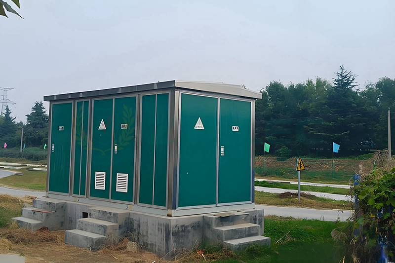
Site Selection Requirements: The installation site should be chosen considering power supply radius, load distribution, and accessibility. To minimize energy loss, the substation should be located near the load center.
Foundation Construction: The concrete foundation must be designed according to the weight and size of the substation, ensuring strength and levelness within ±5 mm. Cable entry/exit paths and grounding electrode positions should be pre-embedded for easy installation.
2. Equipment Inspection
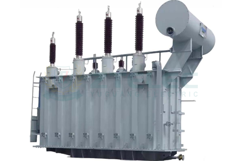
Appearance Inspection: Before installation, check all components, including the enclosure, transformer, and switchgear, for deformation, corrosion, or missing accessories. Ensure nameplates and parameters meet design specifications.
Internal Component Inspection: Verify that internal parts are properly fixed and connected. Test mechanical flexibility of circuit breakers and switches, and ensure interlock systems operate reliably to prevent misoperation.
Insulation Testing: Use an insulation resistance tester to measure insulation resistance between windings, the transformer core, and internal busbars to ensure electrical safety.
Installation Process of European-Type Prefabricated Substations
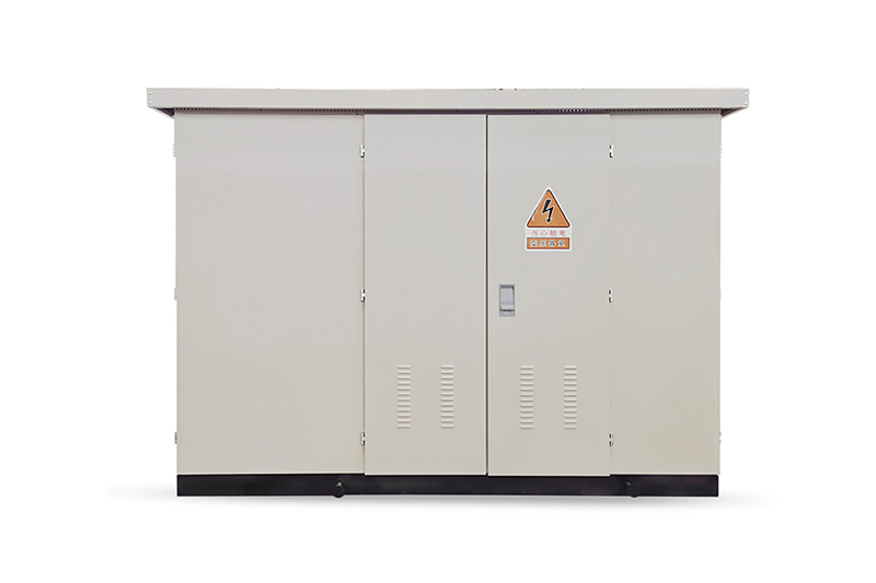
1. Installation of the Substation Enclosure
Hoisting Operation: Use a suitable crane and lifting straps at designated lifting points. Ensure smooth lifting to avoid vibration or collision. During placement, align the substation on the foundation precisely using a level gauge.
Position Calibration: Adjust with shims or pads to achieve required level accuracy. Anchor bolts should be installed and tightened according to torque specifications.
2. Electrical Connection Standards
Cable Connection: Confirm cable type and specification before connection. Strip insulation to the correct dimensions and tightly crimp the terminal lug. Install stress cones to prevent electric field concentration and firmly fix cables to prevent tension or bending damage.
Busbar Connection: Tighten all busbar joints and check phase sequence accuracy (A-green, B-yellow, C-red). Maintain electrical clearance of at least 125 mm and creepage distance of not less than 240 mm for 10 kV systems.
3. Grounding System Installation
Installation of Grounding Electrodes: Grounding electrodes must be installed per design requirements—typically 50 mm × 5 mm angle steel with a minimum length of 2.5 m and spacing of 5 m. Ensure good soil contact; apply resistance-reducing agents if needed.
Grounding Conductor Connection: Connect the enclosure, transformer neutral, and switchgear grounding busbar to the grounding network. Copper grounding conductors should have a cross-section ≥25 mm². All joints must be secure and corrosion-resistant.
Post-Installation Inspection and Commissioning
1. Appearance Re-Inspection
After installation, confirm that the substation enclosure is stable with no tilting or displacement. Check all cable and busbar connections for overheating, discoloration, or looseness. Re-tighten any loose joints immediately.
2. Electrical Performance Commissioning
Insulation Performance Test: Recheck insulation resistance of transformer and switchgear. Perform AC withstand voltage tests — for a 10 kV transformer, apply 30 kV for 1 minute to verify insulation strength.
Operational Parameter Testing: Energize the substation and measure no-load voltage and current. Check all circuit parameters to confirm they meet design requirements. Test relay protection devices to ensure accurate settings and reliable tripping during overcurrent events.
3. Safety Facilities Inspection
Verify all safety signage such as “Stop! High Voltage Hazard!” is visible and correctly placed. Inspect firefighting equipment for pressure and validity. Measure grounding resistance—it should not exceed 4 Ω to ensure personnel safety.
Strict adherence to the installation specifications of European-type prefabricated substations is essential for ensuring long-term stability, reducing maintenance costs, and preventing accidents. A well-executed installation requires careful site preparation, standardized construction, and thorough inspection to guarantee optimal power system performance.