How to Choose the Right Transformer Capacity for Your Facility
Time:2026-08-13 Auther:ZTelec-www.ztelectransformer.com
Selecting the right transformer capacity is one of the most important decisions when designing or upgrading an electrical distribution system. A transformer that is too small can become overloaded, overheat, and reduce system reliability, while an unnecessarily large transformer can increase capital costs and no-load energy losses.
Whether you are designing a manufacturing plant, commercial building, hospital, data center, renewable energy facility, or utility substation, the transformer should be sized according to the facility’s actual electrical demand, future expansion plans, voltage requirements, operating environment, load characteristics, and applicable electrical standards.
This transformer sizing guide explains how to calculate the required kVA or MVA rating, evaluate peak and average loads, account for future expansion, select between dry type and oil immersed transformers, and avoid common transformer sizing mistakes.

What Is Transformer Capacity?
Transformer capacity is the maximum apparent power that a transformer is designed to supply continuously under specified operating conditions without exceeding its thermal, insulation, or other applicable limits.
Transformer capacity is normally expressed in kVA for smaller distribution transformers and MVA for larger power transformers.
For example, common distribution transformer ratings include 315 kVA, 500 kVA, 630 kVA, 800 kVA, 1000 kVA, 1250 kVA, 1600 kVA, and 2000 kVA. Larger industrial and utility transformers may be rated at several MVA or hundreds of MVA.
Why Transformer Capacity Matters
Reliability: Correct transformer sizing helps prevent continuous overloading, excessive temperature rise, and premature insulation ageing.
Energy efficiency: Transformer losses include no-load losses and load losses. An oversized transformer can operate with relatively high no-load losses compared with its actual load, while an undersized transformer can experience excessive load losses.
Capital cost: A larger transformer generally requires greater initial investment and may also require larger switchgear, cables, foundations, rooms, and protection equipment.
Future expansion: Appropriate capacity planning provides enough reserve for expected load growth without unnecessarily purchasing excessive capacity at the beginning of the project.
Transformer Capacity vs Connected Load
One of the most important concepts in transformer sizing is the difference between connected load and maximum demand.
Connected load is the sum of the rated power of all equipment connected to the electrical system. Maximum demand represents the highest expected simultaneous demand of the facility.
These values are often different because not every motor, HVAC system, lighting circuit, production machine, or other electrical load operates at full rated capacity at the same time.
| Term | Meaning | Importance for Transformer Sizing |
|---|---|---|
| Connected Load | Total rated load of connected equipment | Provides the starting point for load assessment |
| Maximum Demand | Highest expected simultaneous electrical demand | Critical for determining transformer capacity |
| Average Load | Average power demand over a specified period | Important for evaluating energy consumption and loading |
| Peak Load | Highest measured or calculated demand | Important for thermal and operational capacity |
| Future Load | Expected additional demand from expansion | Determines required capacity margin |
How to Calculate Transformer Capacity
A practical transformer sizing calculation generally follows this sequence:
Connected Load → Demand Assessment → Power Factor → Peak Demand → Future Growth → Environmental Derating → Standard Transformer Rating
Step 1: Calculate the Connected Load
Prepare a complete list of electrical equipment and record the rated power of each load.
Typical facility loads include motors, pumps, compressors, HVAC systems, lighting, elevators, production machinery, battery chargers, UPS systems, data center equipment, heating systems, and auxiliary equipment.
For example, assume a facility has a total connected apparent load of 1,200 kVA.
Step 2: Determine the Demand Factor
The demand factor accounts for the fact that the entire connected load may not operate simultaneously at its maximum rating.
The basic relationship is:
Maximum Demand = Connected Load × Demand Factor
If the connected load is 1,200 kVA and the engineering study establishes a demand factor of 0.85:
1,200 kVA × 0.85 = 1,020 kVA
The estimated maximum demand is therefore 1,020 kVA.
Demand factors should not be selected using a universal percentage. They depend on the facility type, operating schedule, equipment characteristics, electrical code requirements, and actual load data. Where reliable measured data are available, they are generally more valuable than a generic assumption.
Step 3: Consider Power Factor
Transformer capacity is expressed in apparent power, or kVA, rather than simply kW.
The relationship between real power and apparent power is:
kVA = kW ÷ Power Factor
For example, if the facility has a maximum real power demand of 800 kW and an operating power factor of 0.90:
800 kW ÷ 0.90 = 889 kVA
This means a transformer must be selected based on approximately 889 kVA of apparent power before considering future growth, environmental derating, redundancy, or other design requirements.
Step 4: Account for Future Load Growth
Future expansion should be considered during transformer selection, especially for manufacturing facilities, commercial developments, data centers, and infrastructure projects.
A common planning approach is to reserve a capacity margin, but the appropriate margin should be based on the actual expansion plan rather than automatically adding 20% or 30% to every project.
For example, if the calculated maximum demand is 1,020 kVA and the project requires a 20% planning margin:
1,020 kVA × 1.20 = 1,224 kVA
The next available standard transformer rating may therefore be considered, subject to detailed engineering analysis.
Step 5: Apply Environmental and Operating Conditions
Transformer capacity is specified under defined service conditions. High ambient temperature, high altitude, restricted ventilation, enclosure design, harmonic loading, and other environmental factors can affect the transformer’s thermal performance.
For high-altitude installations, the manufacturer should confirm whether derating or special cooling arrangements are required.
For high-temperature environments, the transformer may require a suitable design adjustment or a higher rated capacity depending on the specified operating conditions.
Step 6: Select the Appropriate Standard Rating
Once the calculated requirement is established, select a commercially available transformer rating that meets the actual design conditions.
For example, if the engineering calculation indicates approximately 1,224 kVA, possible standard ratings may include 1250 kVA or a larger rating depending on the required reserve margin, operating conditions, transformer temperature rise, harmonic content, redundancy strategy, and future expansion plan.
The goal is not simply to select the largest available transformer. The selected rating should provide an appropriate balance between capacity, efficiency, cost, reliability, and future requirements.
Common Transformer Capacity Ratings
| Transformer Rating | Typical Applications |
|---|---|
| 100 kVA | Small commercial buildings, workshops, auxiliary loads |
| 160 kVA | Small commercial and light industrial applications |
| 250 kVA | Commercial facilities, small factories, distributed power systems |
| 315 kVA | Commercial buildings, industrial facilities, infrastructure projects |
| 500 kVA | Commercial buildings, factories, renewable energy systems |
| 630 kVA | Industrial plants, commercial complexes, distribution substations |
| 800 kVA | Medium-sized industrial and commercial facilities |
| 1000 kVA | Industrial plants, data centers, commercial buildings, substations |
| 1250 kVA | Industrial facilities, commercial complexes, renewable energy projects |
| 1600 kVA | Large commercial and industrial facilities |
| 2000 kVA | Large industrial plants, data centers, renewable energy projects |
| 2500 kVA and above | Large industrial, infrastructure, and utility applications |
These application examples are general guidelines. Actual transformer selection depends on voltage, load profile, installation conditions, standards, protection requirements, and the manufacturer’s available ratings.
Dry Type vs Oil Immersed Transformer Capacity
The choice between a dry type transformer and an oil immersed transformer should not be based solely on capacity.
Dry Type Transformer
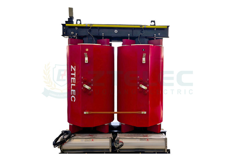
Dry type transformers use air and solid insulation systems rather than conventional insulating oil. Cast resin transformers are widely used in commercial buildings, hospitals, data centers, factories, transportation facilities, and indoor substations.
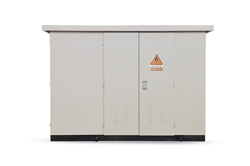
They can also be designed for outdoor applications when the enclosure and environmental protection are suitable for the site.
Dry type transformers are particularly attractive when fire-risk management, indoor installation, environmental considerations, and reduced liquid-related maintenance are important.
Oil Immersed Transformer
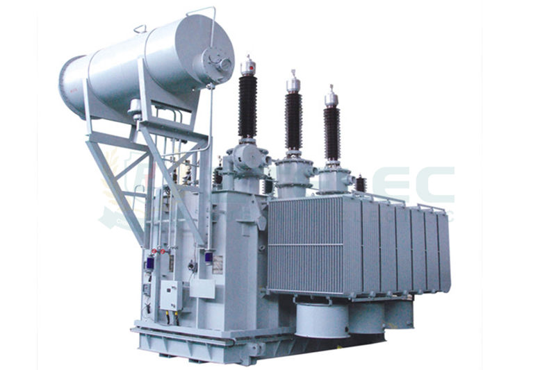
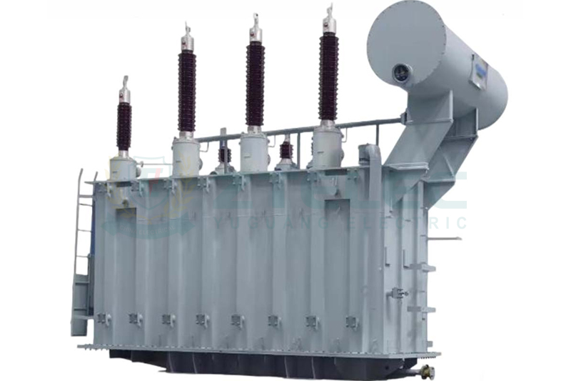
Oil immersed transformers use insulating liquid for electrical insulation and heat transfer. They are widely used in utility substations, industrial facilities, renewable energy plants, and outdoor distribution systems.
The liquid cooling system provides effective heat transfer and supports a broad range of high-capacity transformer designs.
Oil immersed transformers are not necessarily limited to outdoor installation. Indoor use can be possible when the installation meets applicable fire protection, ventilation, containment, and electrical requirements.
How Voltage Affects Transformer Capacity Selection
Transformer capacity and voltage must always be evaluated together.
Primary Voltage
The primary voltage is the voltage supplied to the transformer from the utility, generator, or upstream distribution system. Common medium-voltage levels include 6.6 kV, 10 kV, 11 kV, 13.8 kV, 22 kV, and 33 kV, depending on the country and electrical network.
Secondary Voltage
The secondary voltage must match the facility’s electrical distribution requirements. Common low-voltage systems include 400 V, 415 V, 480 V, and other regional standards.
Voltage Regulation
Voltage regulation describes the change in secondary voltage as transformer loading changes.
For facilities with sensitive equipment, large motors, long cable runs, or rapidly changing loads, voltage regulation should be carefully evaluated during transformer selection.
How Load Characteristics Affect Transformer Sizing
Motor Loads
Large motors can create significant starting currents. Motor starting conditions should therefore be evaluated separately from normal running load.
Depending on the motor type and starting method, starting current can be several times the normal full-load current. Direct-on-line starting, soft starters, and variable frequency drives can produce substantially different electrical characteristics.
For facilities with large motors, transformer impedance, voltage dip, short-circuit capacity, and starting performance should be included in the engineering study.
Nonlinear Loads and Harmonics
Modern facilities often contain nonlinear loads such as variable frequency drives, UPS systems, rectifiers, data center power supplies, and other power electronic equipment.
Harmonic currents can increase transformer losses and heating. Where significant harmonic distortion is expected, the transformer should be evaluated for harmonic loading and may require an appropriate design, K-factor rating, or other mitigation strategy depending on the application.
Intermittent Loads
Some facilities have large loads that operate only for short periods. Examples include cranes, welders, compressors, elevators, and certain production machines.
These loads can create short-duration peaks that should be considered when determining transformer thermal capacity and voltage stability.
Transformer Efficiency and Losses
Transformer efficiency should be evaluated using both no-load losses and load losses.
No-Load Losses
No-load losses primarily occur in the magnetic core and are present whenever the transformer is energized. They are therefore important when a transformer remains energized continuously, even when the facility load is relatively low.
Load Losses
Load losses are mainly associated with winding resistance and other load-dependent effects. They increase as transformer loading increases and are approximately proportional to the square of current for the resistive component.
For this reason, an oversized transformer is not automatically more energy efficient. At very light loading, its no-load losses may represent a larger proportion of the total energy consumption.
How to Compare Transformer Efficiency
When comparing transformer quotations, review the manufacturer’s guaranteed no-load loss, load loss, total loss, impedance, temperature rise, and efficiency data rather than relying on a general efficiency percentage.
Transformer Capacity and Short-Circuit Withstand
Transformer capacity selection must also consider the available fault current of the electrical system.
A transformer must be designed to withstand the thermal and mechanical stresses associated with short-circuit conditions for the duration specified by the applicable standard and system protection scheme.
Transformer impedance is particularly important because it affects prospective short-circuit current. Increasing transformer impedance can reduce fault current but may also affect voltage regulation and motor starting performance.
Therefore, transformer impedance should be selected as part of the overall electrical system design rather than treated as an isolated parameter.
Transformer Capacity and Redundancy
For critical facilities, transformer capacity is closely connected to the required redundancy level.
Data centers, hospitals, semiconductor plants, industrial processes, and other critical facilities may use multiple transformers instead of relying on one large transformer.
For example, a facility requiring approximately 2,000 kVA could potentially use one 2,500 kVA transformer or multiple transformers depending on the required redundancy architecture, maintenance strategy, load distribution, and fault tolerance.
The correct configuration depends on whether the project requires N, N+1, 2N, or another redundancy strategy.
Step-by-Step Transformer Sizing Example
Example 1: Commercial Building
Assume an office building has a connected apparent load of 800 kVA.
The engineering study establishes a maximum demand factor of 0.85:
800 kVA × 0.85 = 680 kVA
Assume the project requires a 20% planning margin:
680 kVA × 1.20 = 816 kVA
A 1000 kVA dry type transformer could be evaluated as the next practical standard rating, subject to the project’s actual load profile, efficiency requirements, installation conditions, and future expansion plan.
Example 2: Industrial Manufacturing Plant
Assume a manufacturing facility has a connected apparent load of 5,000 kVA and an established maximum demand factor of 0.90.
5,000 kVA × 0.90 = 4,500 kVA
With a 20% planning margin:
4,500 kVA × 1.20 = 5,400 kVA
A transformer rating above this calculated requirement may be evaluated, such as a 6,000 kVA oil immersed transformer, depending on standard ratings, motor starting requirements, harmonic loading, redundancy, ambient conditions, and the facility’s expansion plan.
Example 3: Renewable Energy Facility
Assume a renewable energy facility has an apparent power requirement of 2,000 kVA. If the engineering study establishes a maximum demand of 1,900 kVA and a 15% planning margin is required:
1,900 kVA × 1.15 = 2,185 kVA
A 2,500 kVA transformer may be evaluated, but the final selection must also consider generation profiles, bidirectional power flow, harmonic content, ambient temperature, altitude, grid connection requirements, and the transformer’s cooling and insulation system.

Common Transformer Sizing Mistakes
1. Undersizing the Transformer
An undersized transformer may operate close to or above its rated thermal capacity for extended periods. This can increase temperature rise, accelerate insulation ageing, increase losses, and reduce reliability.
The solution is to calculate actual maximum demand and evaluate future expansion, environmental conditions, harmonics, motor starting, and emergency loading requirements.
2. Oversizing the Transformer
Oversizing increases the initial equipment cost and can increase no-load energy losses. A transformer operating at very light load may also have poorer economic performance than a correctly sized transformer.
The solution is to select an appropriate capacity margin based on actual engineering requirements rather than automatically selecting the largest available rating.
3. Ignoring Future Expansion
A transformer that is adequate today may become insufficient after production capacity, building space, HVAC systems, charging infrastructure, or other electrical loads are added.
Future expansion should be included in the load forecast before the transformer is ordered.
4. Ignoring Ambient Temperature and Altitude
High ambient temperature and high altitude can affect transformer thermal performance. The manufacturer’s design should therefore be evaluated using the actual site conditions.
5. Ignoring Harmonic Loads
Facilities with UPS systems, variable frequency drives, rectifiers, and other nonlinear loads should evaluate harmonic currents and their potential impact on transformer heating and losses.
6. Selecting a Transformer Based Only on kVA
Two transformers with the same kVA rating can have very different losses, impedance, temperature rise, insulation levels, enclosure configurations, sound levels, and environmental capabilities.
A complete technical comparison is essential before purchasing.
Transformer Standards and Capacity Selection
Transformer capacity selection should be performed together with the applicable electrical standards and project specifications.
For applicable dry type power transformers, IEC 60076-11 is an important international standard. For general power transformer requirements, other parts of the IEC 60076 series may also apply.
Depending on the market and project location, additional requirements may come from IEEE standards, national standards, utility specifications, building codes, fire codes, and electrical installation regulations.
For example, a transformer intended for the United States may need to comply with applicable NEC requirements and project-specific utility or equipment standards, while projects in other countries may follow IEC-based or national standards.
Dry Type Transformer Capacity Selection
Dry type transformers are commonly selected for applications where indoor installation, fire-risk management, environmental considerations, and reduced liquid-related maintenance are important.
| Capacity | Common Applications |
|---|---|
| 315 kVA | Small industrial facilities, commercial buildings, auxiliary distribution |
| 500 kVA | Commercial buildings, factories, renewable energy systems |
| 630 kVA | Industrial facilities and commercial distribution systems |
| 800 kVA | Medium-sized commercial and industrial facilities |
| 1000 kVA | Data centers, factories, commercial buildings, substations |
| 1250 kVA | Large commercial and industrial facilities |
| 1600 kVA | Large industrial plants and infrastructure projects |
| 2000 kVA | Large industrial, data center, and renewable energy applications |
| 2500 kVA and above | High-capacity industrial and infrastructure projects |
Dry type transformer capacity is not limited to a specific universal maximum. Available ratings depend on manufacturer technology, voltage class, cooling design, installation environment, and project requirements.
Oil Immersed Transformer Capacity Selection
Oil immersed transformers are widely used for utility distribution, industrial substations, renewable energy projects, and high-capacity power systems.
Their liquid cooling system can provide effective heat transfer and makes the technology suitable for a wide range of medium- and high-capacity applications.
Common oil immersed transformer ratings can range from small distribution transformers to large utility power transformers rated in the tens or hundreds of MVA.
The correct rating should be determined from the facility’s calculated demand, system voltage, fault level, loading profile, environmental conditions, cooling requirements, and future expansion plan.
Maintenance Considerations When Selecting Transformer Capacity
Dry Type Transformer Maintenance
Routine maintenance typically includes inspection of insulation, terminals, connections, cooling passages, ventilation, temperature monitoring, and enclosure condition.
Dust and moisture should be controlled because contamination can affect insulation performance and cooling.
Thermal imaging can be used as part of a condition-based maintenance program to identify abnormal heating at electrical connections and other components.
Oil Immersed Transformer Maintenance
Oil immersed transformers require monitoring of the transformer tank, bushings, seals, cooling equipment, protection devices, and insulating liquid.
Depending on transformer importance and operating conditions, oil diagnostics can include moisture testing, dielectric strength testing, acidity assessment, and dissolved gas analysis.
Oil replacement should not be performed according to a universal fixed interval. The appropriate maintenance action should be based on oil condition, test results, transformer design, operating conditions, and the manufacturer’s recommendations.
Future Trends in Transformer Capacity Planning
Smart Transformer Monitoring
Digital sensors and condition-monitoring systems are increasingly being used to measure transformer temperature, load, voltage, current, and other operating parameters.
Real-time data can help operators identify overload conditions and optimize transformer utilization.
Modular Transformer Systems
Facilities with rapidly changing demand may benefit from multiple-transformer or modular power distribution architectures. These configurations can provide greater flexibility for future expansion and maintenance.
High-Efficiency Transformers
Improved core materials, optimized winding designs, and low-loss manufacturing technologies are helping reduce transformer energy consumption.
Amorphous metal core transformers are one example of a technology designed to reduce no-load losses in suitable distribution applications.
Renewable Energy Integration
Solar farms, wind farms, battery energy storage systems, and hybrid energy systems can introduce variable loads, changing power flow, harmonics, and other operating characteristics.
Transformer capacity planning for these applications should therefore consider both the maximum apparent power and the dynamic characteristics of the electrical system.
How to Choose the Right Transformer Capacity
The following engineering sequence provides a practical approach:
1. Determine the connected load.
2. Identify the expected maximum demand.
3. Evaluate power factor and calculate apparent power where necessary.
4. Consider motor starting, nonlinear loads, harmonics, and other special loads.
5. Forecast future electrical demand.
6. Apply appropriate environmental and altitude considerations.
7. Select the transformer technology and cooling method.
8. Check primary voltage, secondary voltage, impedance, insulation level, and frequency.
9. Compare no-load losses and load losses.
10. Verify short-circuit withstand capability.
11. Evaluate redundancy and system reliability requirements.
12. Select the nearest suitable standard transformer rating and confirm the final design with the transformer manufacturer or qualified electrical engineer.
Frequently Asked Questions About Transformer Capacity
How do I calculate the required transformer capacity?
Start with the connected load, determine the maximum demand using actual load data or an appropriate demand assessment, convert kW to kVA using the expected power factor where necessary, and then consider future growth, environmental conditions, harmonics, motor starting, and redundancy requirements.
What transformer capacity do I need for a 1 MW facility?
A 1 MW facility does not automatically require a 1 MVA transformer. Transformer capacity depends on power factor, maximum demand, load profile, future expansion, harmonic content, and operating conditions. For example, at a 0.90 power factor, 1 MW corresponds to approximately 1.11 MVA of apparent power if the full 1 MW is demanded simultaneously.
How much transformer capacity should I reserve for future expansion?
There is no universal percentage that applies to every project. A capacity margin should be based on the facility’s actual expansion plan, expected load growth, project schedule, and economic analysis. A staged or modular transformer configuration may be more economical than installing excessive capacity from the beginning.
Is a larger transformer always better?
No. An oversized transformer can increase capital costs and no-load energy losses. The ideal transformer is large enough to meet the maximum expected demand and required reserve while maintaining acceptable efficiency and thermal performance.
What happens if a transformer is undersized?
An undersized transformer can experience excessive loading, higher temperature rise, increased load losses, voltage regulation problems, accelerated insulation ageing, and reduced service life. Severe or prolonged overloading can lead to equipment failure.
Can a dry type transformer be used outdoors?
Yes. Dry type transformers can be designed for outdoor applications when the enclosure, insulation system, ventilation, environmental protection, and other design parameters are suitable for the site conditions.
Which transformer is better for a large industrial facility?
Both dry type and oil immersed transformers can be suitable for industrial facilities. Dry type transformers may be advantageous for indoor installations and applications with strict fire or environmental requirements, while oil immersed transformers are widely used for large outdoor substations and high-capacity systems because of their effective liquid cooling and broad rating range.
What transformer capacity is suitable for a data center?
Data center transformer capacity should be based on the maximum IT load, mechanical load, UPS configuration, cooling system, power factor, redundancy architecture, future expansion, and required electrical availability. Multiple transformers may be used to achieve N+1 or 2N redundancy.
Does altitude affect transformer capacity?
Yes. High altitude can affect cooling and dielectric performance, particularly for air-cooled equipment. The transformer manufacturer should evaluate the actual installation altitude and determine whether special design measures or derating are required.
Choosing the right transformer capacity requires more than adding up the rated power of all electrical equipment. A reliable transformer sizing process considers connected load, maximum demand, power factor, future expansion, motor starting, harmonics, environmental conditions, voltage requirements, efficiency, short-circuit withstand capability, redundancy, and applicable standards.
For commercial buildings, data centers, industrial plants, renewable energy projects, and utility substations, the appropriate transformer rating may be significantly different even when the connected load appears similar.
The most effective approach is to calculate the actual maximum apparent power, add a justified planning margin, evaluate site conditions and special loads, and then select the nearest appropriate standard transformer rating.
When comparing dry type transformers and oil immersed transformers, the decision should also consider installation location, fire protection, cooling performance, maintenance, environmental requirements, efficiency, lifecycle cost, and future expansion.
Before placing an order, the final transformer capacity should be verified against the complete electrical design and confirmed by a qualified electrical engineer or experienced transformer manufacturer. Proper transformer sizing can reduce energy losses, improve reliability, extend equipment life, and provide sufficient capacity for the facility’s long-term power requirements.