Neutral Grounding Methods for Distribution Transformers
Time:2026-10-28 Auther:ZTelec-www.ztelectransformer.com
How a transformer neutral is connected to earth looks like a small detail. In practice, it shapes fault current, voltage stress, protection settings, safety and the cost of downtime across the whole power system.
This guide explains the main neutral grounding methods used with distribution transformers, how each one behaves during a ground fault, and what to consider when choosing between them. It also covers practical points for dry cast resin transformers and oil filled transformers.

What Is Neutral Grounding?
Neutral grounding means connecting the neutral point of a transformer winding to earth, either directly or through an impedance. The neutral point is the star (wye) point of the winding, where the three phase windings meet.
The connection method determines what happens when one phase touches earth. That single event is the most common type of fault in power systems, so the grounding design has a large effect on reliability and safety.
Why Grounding Matters
A well-chosen grounding method helps to achieve four goals.
Limit overvoltages. Without a defined earth reference, a ground fault can cause voltage stress on the healthy phases and on insulation.
Control fault current. The current must be high enough for protection to detect, yet low enough to avoid damage to windings, cables and switchgear.
Protect people and equipment. Lower fault energy reduces arc flash hazards and touch voltage risks.
Support continuity of supply. Some methods allow the system to keep running during a first fault, which matters in continuous processes.
The Main Neutral Grounding Methods
Engineers usually group neutral grounding into five categories. Each one balances fault current, overvoltage and service continuity differently.
1. Solid Grounding
In solid grounding, the neutral is connected directly to earth with no intentional impedance. This is the simplest arrangement, and it is very common on low voltage 400/230 V distribution systems.
During a phase-to-earth fault, a large current flows. The fault current can be comparable to a three-phase short circuit, so protective devices operate quickly and clearly.
Advantages: Simple design, reliable fault detection, low overvoltage on the healthy phases, and the ability to supply single-phase loads from phase to neutral.
Limitations: High fault current causes mechanical and thermal stress on the transformer and increases arc flash energy. Each ground fault normally trips the circuit, which interrupts supply.
2. Low Resistance Grounding
Low resistance grounding places a neutral grounding resistor (NGR) between the neutral and earth. The resistor limits the ground fault current to a defined level, often in the range of a few hundred amperes. Typical values depend on system voltage and the protection design.
The current remains large enough for selective protection with overcurrent or earth fault relays. Because the fault is cleared quickly, the resistor only needs a short-time rating.
Advantages: Much lower damage and arc flash risk than solid grounding, plus good selectivity and controlled transient overvoltages.
Limitations: The faulted feeder is tripped, so supply is interrupted. Single-phase line-to-neutral loads cannot be supplied from the grounded neutral on medium voltage systems.
3. High Resistance Grounding
High resistance grounding uses a resistor that limits ground fault current to a very small value, typically only a few amperes up to about ten. The system can keep running during a first ground fault while an alarm alerts maintenance staff.
Designers must make sure the resistor current is at least as large as the system’s capacitive charging current. Otherwise, transient overvoltages can build up during intermittent faults.
Advantages: Maximum continuity of supply, minimal fault damage and a low shock hazard at the fault point.
Limitations: The first fault must be located and repaired promptly, because a second fault on another phase becomes a phase-to-phase fault. Ground fault detection and monitoring are essential. This method is most often used in industrial systems at lower voltages.
4. Reactance Grounding
Reactance grounding uses a reactor between the neutral and earth. It limits fault current while keeping the zero-sequence reactance in a controlled range.
It is less common than resistance grounding. Its main drawback is that, under some conditions, it can allow higher transient overvoltages than a resistor, so it needs careful study.
5. Resonant Grounding (Petersen Coil)
In resonant grounding, an arc suppression coil is connected to the neutral and tuned to the network’s capacitance to earth. During a single-phase fault, the coil’s inductive current largely cancels the capacitive fault current.
Many temporary faults on overhead lines, such as those caused by lightning or tree contact, extinguish by themselves. This method is widely used in European medium voltage networks, especially where overhead lines are common.
Advantages: Very low fault current, self-clearing of transient faults and high supply continuity.
Limitations: Requires tuning, careful monitoring and specialized protection. Costs are higher than for simple resistor grounding.
Ungrounded (Isolated Neutral) Systems
Some systems have no intentional neutral connection to earth. They usually rely on a delta winding. The system can operate through a first fault, but intermittent arcing faults may produce high transient overvoltages, and locating the fault can be difficult. Many modern designs prefer one of the grounded methods above.
Neutral Grounding Methods Compared
The table below summarizes the typical behavior of each method. Values are general guidance, so always confirm them in a system study.
| Method | Ground Fault Current | Overvoltage Risk | Supply After First Fault | Typical Use |
|---|---|---|---|---|
| Solid | Very high | Low | Trips | Low voltage distribution |
| Low resistance | Moderate, limited by NGR | Controlled | Trips | Medium voltage industrial and utility feeders |
| High resistance | Very low | Controlled if sized correctly | Continues with alarm | Continuous process plants |
| Reactance | Moderate to high | Higher than resistance | Trips | Special cases, generators |
| Resonant | Very low | Low when tuned | Continues | Overhead medium voltage networks |
How Transformer Winding Connection Affects Grounding
The winding connection decides whether a usable neutral exists and how zero-sequence current flows.
Delta-Star Transformers
Distribution transformers commonly use a delta primary and a star secondary, such as Dyn11. The star secondary provides a neutral for grounding, while the delta winding traps zero-sequence currents and keeps ground faults on the secondary side from flowing into the upstream network.
Star-Star Connections
Star-star transformers can pass zero-sequence current between systems and may need a tertiary delta winding or careful design to control unbalance and harmonics.
Creating a Neutral with a Zig-Zag Transformer
When a system is delta connected and has no neutral, a zig-zag or star-delta grounding transformer can create an artificial neutral point. The neutral grounding resistor is then connected to that point.

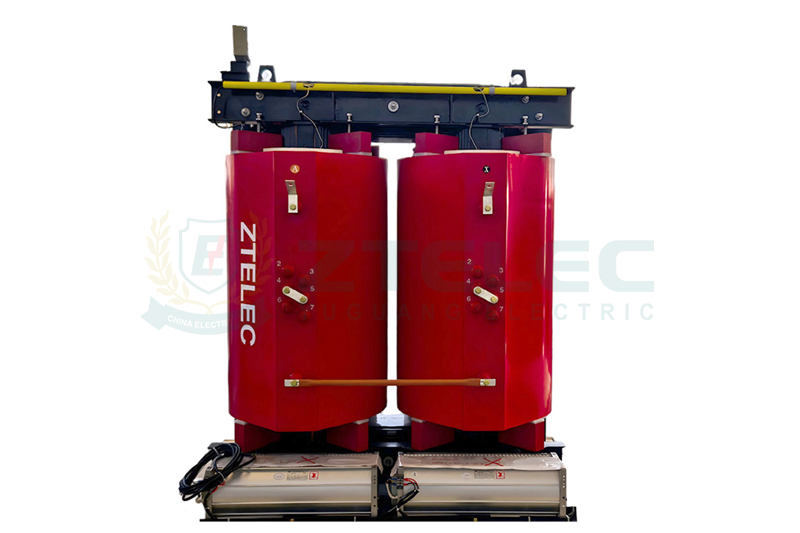
Applying Neutral Grounding to Dry Cast Resin Transformers
Dry cast resin transformers are widely used in buildings, hospitals, data centers, shopping malls and tunnels, where fire safety is a priority.
Practical Considerations
The neutral terminal is brought out on the low voltage side and is easy to access inside the enclosure. A neutral grounding resistor can be installed nearby, often in its own ventilated cabinet.
Because these installations are usually indoors, the resistor’s heat dissipation, ventilation and enclosure protection class should be planned together with the transformer room.
Low fault current methods are attractive for dry cast resin transformers, since limiting fault energy reduces the stress on cast coils and surrounding equipment. Always confirm the neutral connection and insulation level with the manufacturer.
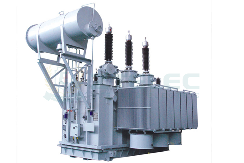
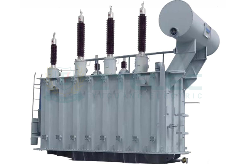
Applying Neutral Grounding to Oil Filled Transformers
Oil filled transformers are typically installed outdoors or in dedicated substations, and are common in utility and industrial networks.
Practical Considerations
The neutral is brought out through a bushing on the tank. For resistance or reactance grounding, the bushing must have an insulation level suitable for the voltage that can appear at the neutral during a fault.
Neutral current transformers are often installed at the neutral to feed earth fault protection. Because oil filled transformers are exposed to the weather, the grounding resistor enclosure should offer suitable ingress protection and corrosion resistance.
Fault current limiting also helps reduce the risk of internal arcing in an oil filled tank, which can create pressure and, in severe cases, fire. Protection devices such as pressure relief and gas relays work together with the earth fault scheme.
How to Choose the Right Neutral Grounding Method
No single method suits every project. The following questions help to narrow the choice.
What Is the System Voltage?
Low voltage systems commonly use solid grounding. Medium voltage systems often prefer resistance or resonant grounding to limit fault energy.
How Important Is Continuity of Supply?
Continuous process plants may justify high resistance or resonant grounding. Commercial buildings with redundant feeders may accept a trip on the first fault.
What Does the Network Look Like?
Cable networks have large capacitive currents, while overhead lines have more temporary faults. These differences influence whether a resistor or a resonant coil is the better choice.
What Protection Can You Support?
Low fault current systems need sensitive earth fault relays and monitoring. Make sure your protection design and maintenance practices match the chosen method.
What Do Local Standards Require?
Follow applicable codes and standards for your region, such as the IEC 60364 series for low voltage installations and IEEE 142 guidance for industrial and commercial systems. Utility rules may also apply.
Key Specifications for a Neutral Grounding Resistor
When ordering a neutral grounding resistor for a transformer, specify the following points clearly.
System voltage and line-to-neutral voltage. The resistor must be rated for the voltage that appears across it during a fault.
Let-through current. This is the ground fault current you want the resistor to allow.
Time rating. Short-time ratings suit tripping schemes, while continuous or extended ratings suit alarm-only systems.
Enclosure and environment. Choose an enclosure rating suited to indoor or outdoor use, and a material suited to humidity, dust or salt exposure.
Monitoring. Neutral current transformers and resistor monitoring relays improve safety.
Frequently Asked Questions
Can a Transformer Neutral Be Left Ungrounded?
Yes, some systems operate this way, but intermittent faults can create high transient overvoltages and fault location is harder. Most modern distribution designs use an intentional grounding method instead.
Is Resistance Grounding Better Than Solid Grounding?
Neither is better in every case. Resistance grounding reduces fault damage and arc flash energy, while solid grounding is simpler and supplies phase-to-neutral loads. The right choice depends on voltage, load type and protection needs.
Does the Grounding Method Change the Transformer Design?
It can. The neutral terminal or bushing must have a suitable insulation level, and the winding connection must support the chosen scheme. Tell your supplier the grounding method before the design is finalized.
Neutral grounding is a design decision that affects safety, protection and uptime across the whole system. Solid grounding is simple and common at low voltage, resistance grounding limits damage in medium voltage networks, and resonant grounding gives high continuity on overhead systems.
Whether your project uses dry cast resin transformers in a building or oil filled transformers in a substation, define the neutral grounding method early so the transformer, resistor, protection and earthing system are designed together.
Need Help Specifying Your Transformer?
Share your system voltage, winding connection, grounding requirement and installation environment with our team. We can supply dry cast resin transformers and oil filled transformers with neutral terminals, bushings and accessories prepared for your chosen grounding method.