Pad Mounted Transformer: Structure, Standards, and Applications
Time:2025-09-17 Auther:ZTelec-www.ztelectransformer.com
The pad mounted transformer, also known as a combined transformer, originated in the United States. It was introduced to the Chinese market in the 1990s, following the country’s economic opening and promotion of a market economy, and has since experienced rapid development.
![]()
Structure and Design Features
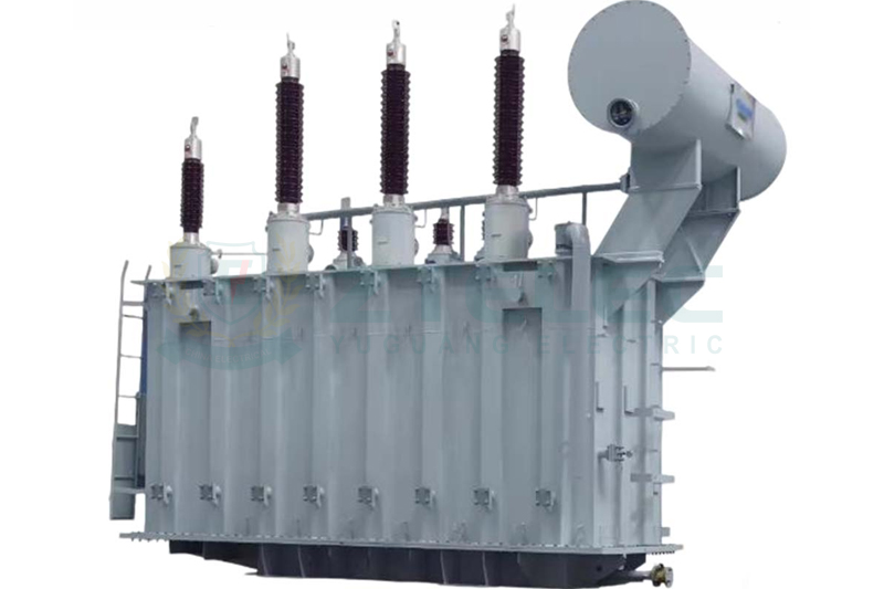
Pad mounted transformers simplify the structure of load switches, ring main switches, and fuses by placing them inside the transformer oil tank, fully immersed in oil. Lightning arresters also use oil-immersed zinc oxide arresters, and the traditional oil pillow is eliminated. The oil tank and radiator are directly exposed to air, resulting in a compact and efficient design.
On the protection side, the high-voltage winding uses fuses to safeguard against short circuits and overloads, while the low-voltage side is equipped with a molded case automatic air circuit breaker providing overload, short-circuit, and ground fault protection. Non-electrical protections include a pressure relief valve, oil temperature gauge, and thermostat, ensuring safe operation.
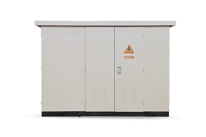
Pad mounted transformers are characterized by small size, minimal footprint, easy installation, and simple maintenance. They are widely applied in urban street lighting, temporary construction power, and boosting systems for new energy projects such as photovoltaic and wind power plants.
Key Technical Standards and Specifications
Pad mounted transformers are designed, manufactured, and tested according to American standards while also meeting the national standards of their deployment region.
American Standards (ANSI/IEEE)
ANSI C57.12.00: General requirements for distribution, power, and voltage-regulating transformers.
ANSI C57.12.90: Transformer testing standard.
ANSI/IEEE C37.60: Standard for outdoor AC high-voltage fuses, switch-disconnectors, and combinations.
UL 347: Standard for medium-voltage AC switchgear.
NEMA TR-27: Standard for prefabricated substations.
Chinese Standards (GB)
For domestic applications, pad mounted transformers comply with the following national and power industry standards:
GB/T 17467: High-voltage/low-voltage prefabricated substations (equivalent to IEC 62271-202).
GB 1094.1/~.5: Power transformer series standards.
DL/T 537: Guidelines for selection, acceptance, and operation of high-voltage/low-voltage prefabricated substations.
![]()
Typical Application Scenarios
Pad mounted transformers are versatile and suitable for multiple applications:
Urban Distribution Networks: Serve residential communities as ring network or terminal nodes, reduce low-voltage cable lengths, and minimize line losses. Commercial centers such as malls, office buildings, and hotels benefit from compact installations and space savings.
Industrial Parks, Factories, and Mines: Provide power and lighting for workshops and production lines. Their compact design allows deployment in limited factory spaces.
Temporary Power: Construction sites and large event venues can use pad mounted transformers as reliable, relocatable power sources. After project completion, units can be moved to the next site.
Renewable Energy: Pad mounted transformers boost low-voltage outputs from small photovoltaic or wind power generators, feeding them into the grid efficiently.
Rural Power Grids: They replace traditional civil distribution rooms, reducing investment costs and construction periods while upgrading rural electricity supply.
Advantages and Considerations
Pad mounted transformers offer a technologically mature, compact, and cost-effective power distribution solution. Their fully insulated design enhances safety, aesthetics, and space efficiency, making them ideal for urban distribution, industrial, and renewable energy applications. While heat dissipation and maintenance may have some limitations, the benefits of compact design, integrated protection, and flexible installation continue to drive adoption globally.
When selecting a pad mounted transformer, consider the application scenario, load requirements, and reliability needs to ensure optimal performance. Assess whether the transformer is suitable for the project or if alternative solutions are necessary.